About TX2RX Automotive Wireless Solutions, LLC
CONCEPT , DESIGN THEN REALITY

The following HydroDrop 101 tutorial will guide you through the procedure of wiring a 3 pump, 4 dump hydraulic setup controlled by a 6 switches. If you are not confident performing the installation, please contact one of our Authorized installers or have a local Lowrider Hydraulic installation shop perform the service. Disclaimer: TX2RX Automotive Wireless Solutions is not responsible for any loss or bodily harm caused by incorrect installations or improper use.

1.00 - Verify items are included with your HydroDrop System: HydroDrop Base Station, Handheld Remote w/rubber case and lanyard, High Current Driver Module and USB charging cable.
2. 00 - Go to our support page and download the correct wiring diagram. For this example, we will be referencing the 3 pump, 4 dump (3, 2 solenoids) diagram.
3.00 - Prior to installation, locate installation area for the HydroDrop base station and kill switch (not included). The HydroDrop Base station is not waterproof and should be installed in an area protected from the weather.
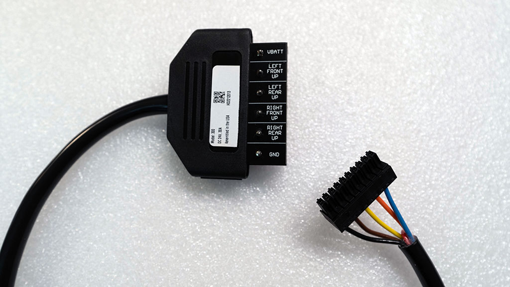
4.00 - To simplify connections, pre-wire the Power Module Cable to Base Station VALVE/SOLENOIDS side output (10 pin terminal). Remove insulation covering and prepare the following wires: BLUE, ORANGE, YELLOW, BROWN and BLACK. See example below.

Cut the High Current Driver Module cable to the desired length before inserting into terminal block receptable. Remove the RED wire, this is not used.

5.00 - Insert the Pump Control Wires into the VALVE/SOLENOID side terminal block (10 pin) BLUE to Pin 2, ORANGE to Pin 4, YELLOW to Pin 6, BROWN to Pin 8, BLACK to Pin 10. Reference photo below.

6.00 - The bottom side of the Power Module Cable is labeled for refence: BLUE = Front Left Up, ORANGE = Rear Left Up, YELLOW = Front Right Up, BROWN = Rear Right Up, BLACK = Ground. Note * the term "PUMP" is synonymous with "UP".
7.00 - Follow your switch assembly instructions and connect to the HydroDrop Base Station input CONTROLLER side (9 pin terminal). The following is an instruction example for a 6 switch panel purchased from an online retailer.
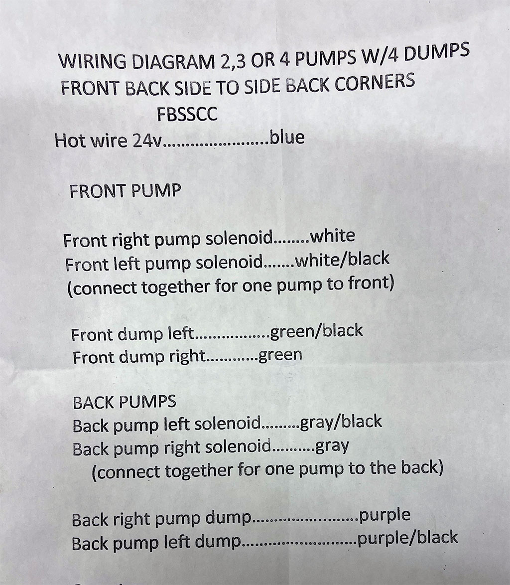
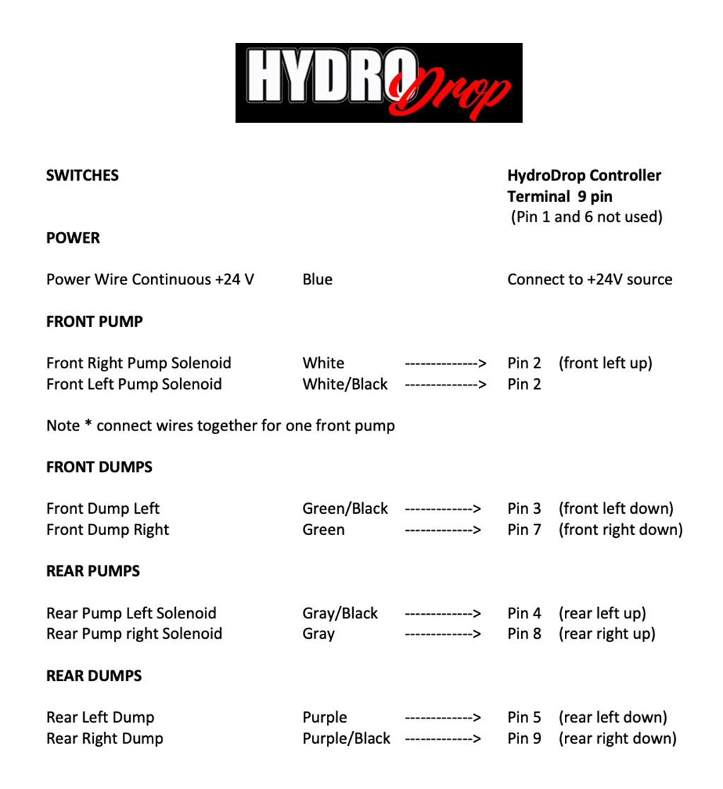
8.00 - For this example 3 pump, 4 dump and 6 switch setup we have mapped the 6 switch panel to the HydroDrop Base Station CONTROLLER side (9 pin terminal). See wiring diagram below for reference. The majority of panel switch kits, switch boxes uses a 9 conductor switch cord. Regardless of the amount of switches on the box or panel 8 conductors are dedicated to 4 wires for pumps (UP) and 4 wires for dumps (DOWN). The 9th wire is used to supply +24V to the switch middle bank terminal(s). Also note, the Front/Left Pump Solenoid wires (white, white/black) are tied together and inserted into Pin 2 of the 9 Pin Terminal Block.
9.00 - Next, we will connect the the Dump Valves. In this tutorial there are 4 dump valves being used, one per each corner of the Lowrider. Each dump valve will connect to the HydroDrop VALVES/SOLENOIDS side (10 pin terminal). The term "DUMP" is synonymous with "DOWN".
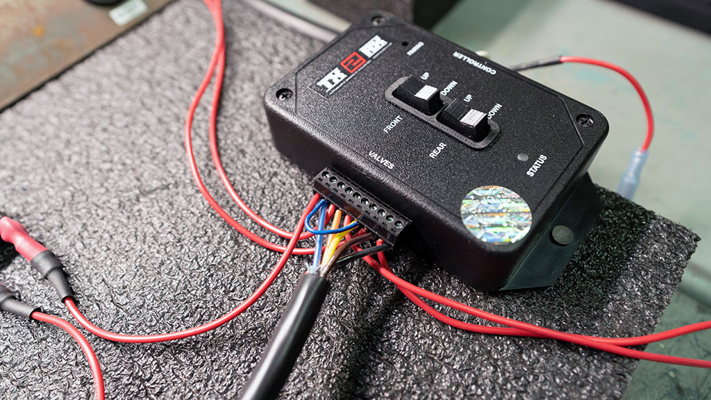
9.10 - There are 4 Dump Valve line outputs on the VALVES/SOLENOID side (10 pin terminal). Pin 3 Front Left Down, Pin 5 Rear Left Down, Pin 7 Front Right Down, Pin 9 Rear Right Down. The dump valves should already have chassis ground.
9.20 - In this tutorial Pin 2 and Pin 6 of the 10 Pin Terminal are jumpered together. This ties both Front Left UP and Front Right UP pump outputs together for the single Front Pump. This will allow you to use both left and right Front UP arrows on the remote. If the jumper is not added only the Front Left UP arrow button will work.
10.00 Connecting +24V and Ground. There are 3 places +24V is required. A) High Current Driver Module Pin 1, B) HydroDrop base station Pin 1 on the 10 pin terminal side, C) Constant +24V to the switch panel. Connect the High Current Driver Module terminal Pin 6 to chassis GROUND.
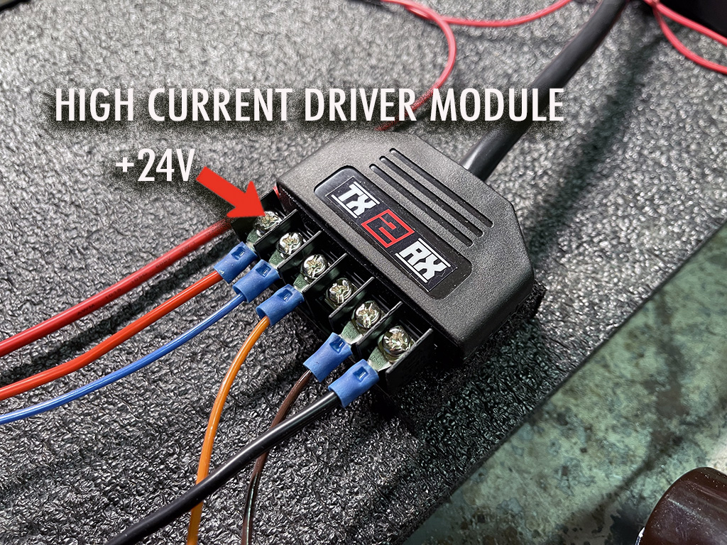
10.10 - A toggle switch is placed between the 10A fuse and +24V source. This is very important and a requirement. The "kill switch" will disable the HydroDrop wireless system when not in use. When the Kill Switch is in the OFF position the panel switch all function as normal. While in the ON position the wireless is active and operational. The base station buttons are also active duiring the ON position.
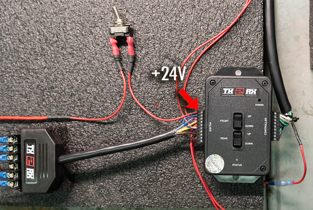
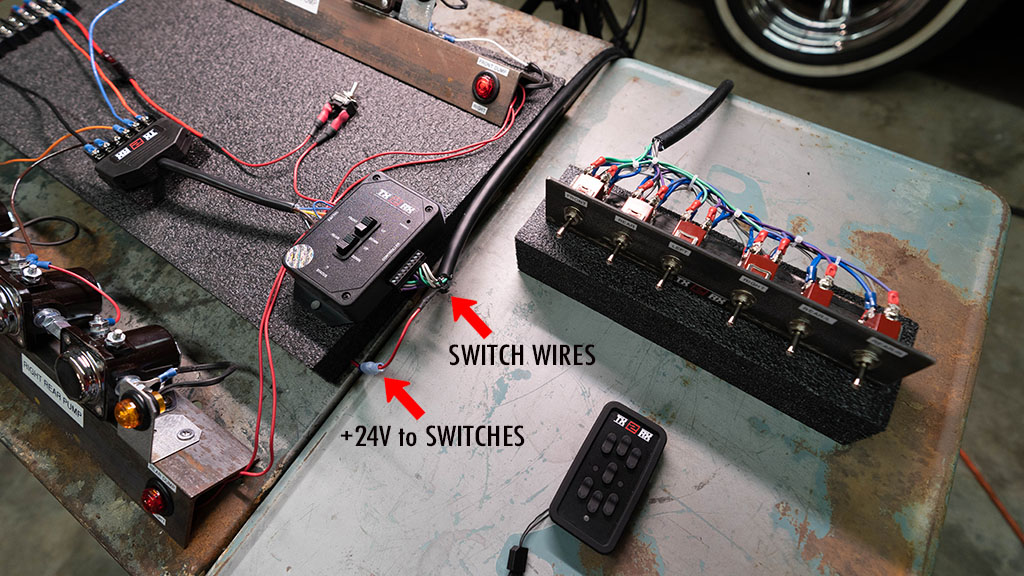
11.00 - A table top setup overview.Verify both terminal blocks are inserted completely and that the terminal screws are securely tightened down. After functional operation has been verified, completely wrap the terminal block of the High Current Driver Module with non-conductive electrical tape. Ensure both the top and bottom areas are not exposed to possible shorting with nearby chassis ground.
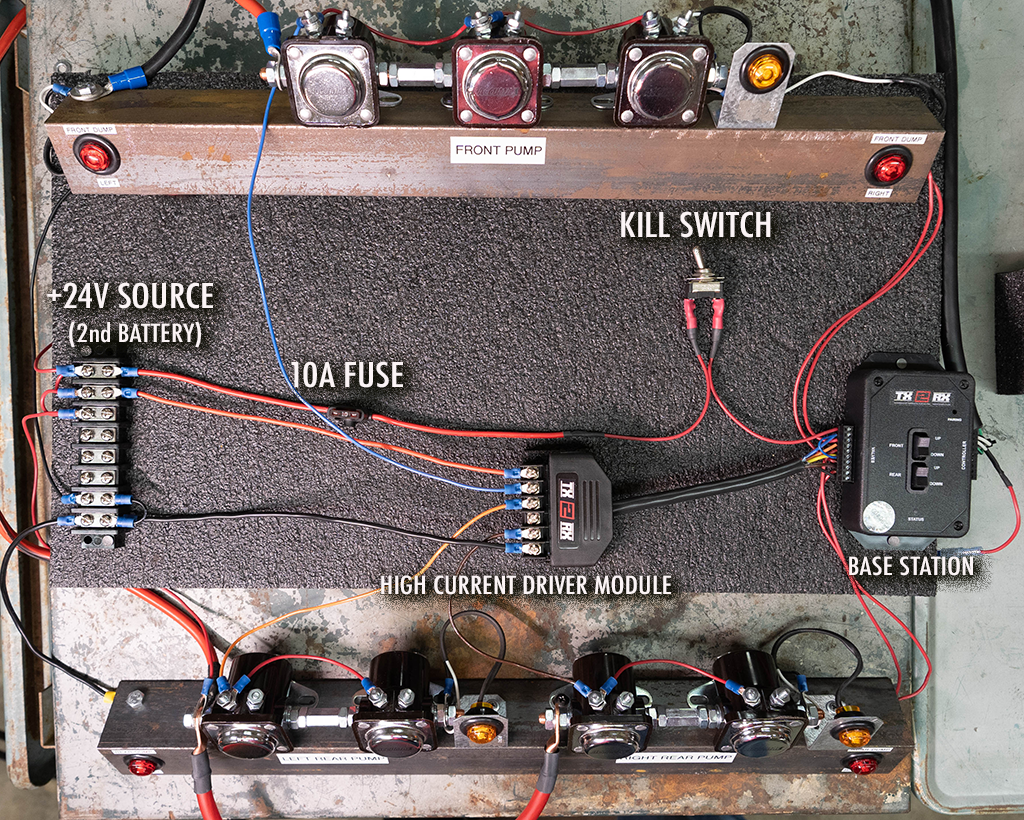
12.00 This concludes the HydroDrop wiring instructions for a 3 pump, 4 dump, 6 switch panel setup. For all other hydraulic setups please go to our support page and download the diagram matching your system. If there is no matching diagram, please contact us for direct support.